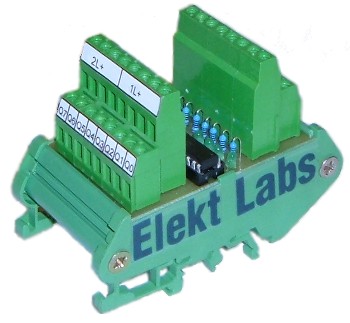
Eight channel optocoupler that is used for galvanic separation signals for input to PLC. It's for use anywhere that ground loops, connection circuits SELV & PELV and any other problems that can occur with the connection of electrically incompatible devices. The optocoupler is designed for industrial environment. For easy installation to the switchboard, there is a 35 mm DIN rail system equipped. To connect the wires, a massive two-storey terminal block is used. The advantage of the optocoupler is that it requires no external power supply for its operation. Every input is equipped with a green LED to signal the activity of the input. Every quadrant of outputs has a common power supply-clamp, L+.
Version "8xOPTOC-M" has emitter output transistors connected to the diode. This makes it able to connect the individual outputs together, which allows for easy expansion if more capacity is needed. If you use this option with the eight channel optocoupler, you can save 4 inputs. When this option is used with two eight channel optocouplers in a 4x4 configuration, then you are able to save 12 inputs.
| Product version | Order number |
|---|---|
| Classical optical delimiter, 24 V version | 8xOPTOC |
| Classical optical delimiter, 12 V version | 8xOPTOC12 |
| Optical separator with the option multiplexer, 24 V version | 8xOPTOC-M |
| Optical separator with the option multiplexer, 12 V version | 8xOPTOC12-M |
1. 8xOPTOC - Classical optical delimiter
For each input signal two clamps are used, Ix and Mx. Output is on clamps Qx and on L+/A must be a 24 Volt (just to one clamp of the four available). So a prepared optocoupler can be connected, for example, with a PLC S7/200.
Attention: It's not possible to use this version for multiplexer function because there would be damage to the output circuits.
2. 8xOPTOC12 - 12 V version of optical separator
In the case that it is required to separate the signals at 12 Volts, this version of optocoupler is available. Its basic properties are:
Attention: It's not possible to use this version for multiplexer function because there would be damage to the output circuits.
3. 8xOPTOC-M - optical delimiter with the optional multiplexer
When using the optocoupler with a multiplexer, the input parts connected are the same as in previous mentioned versions. At output, clamps L+/A are connected to an outputs control unit, for example, the PLC. Pair inputs Q0 and Q4, Q1 and Q5, Q2 and Q6, Q3 and Q7 are connected together and connect inputs from control units. This version is fully compatible with version 8xOPTOC.
| Explanation | |
|---|---|
| I0 - I7 | inputs |
| Q0 -Q7 | outputs |
| M | negative pole 0V |
| L+ | positive pole 24V |
| A0, A1 | address wires when using optical isolators as multiplexer |
| Basic parameters common to all versions | |||
|---|---|---|---|
| Number of inputs | 8 | ||
| Number of outputs | 8 | ||
| Maximal frequency | 10kHz | ||
| Isolation voltage beetwen inputs and outputs | Uiso max = 500V | ||
| Operating temperature | 0 °C to 70 °C | ||
| Mounting | DIN rail 35 mm | ||
| Dimensions (WxHxD) | 50x92x69 mm | ||
| Weight | 130 g |
| Parameters version | 8xOPTOC | ||
|---|---|---|---|
| LED lens color | Green | ||
| INPUT | |||
| Input parameters | 8 x separately isolated | ||
| Input current | IF = (Ui - 3.4)/1.5 [mA], where Ui is input voltage | ||
| Typ. | Max. | ||
| Input voltage | 24V | 30V | |
| Input current | 13.7 mA | 17.7 mA | |
| Output current | 11mA | 14.2mA | |
| OUTPUT | |||
| Output Parameters | 2 x 4 open emitter | ||
| Output current | I = IF*0.8 | ||
| Maximal output voltage | 30V | ||
| Maximal reverse output voltage | 6V | ||
| Parameters version | 8xOPTOC12 | ||
|---|---|---|---|
| LED lens color | Yellow | ||
| INPUT | |||
| Input parameters | 8 x separately isolated | ||
| Input current | IF = (Ui - 3.3)/0.56 [mA], where Ui is input voltage | ||
| Typ. | Max. | ||
| Input voltage | 12V | 16V | |
| Input current | 15.5 mA | 22.7 mA | |
| Output current | 12.4 mA | 18.2mA | |
| OUTPUT | |||
| Output parameters | 2 x 4 open emitter | ||
| Output current | I = IF*0.8 | ||
| Maximal output voltage | 30V | ||
| Maximal reverse output voltage | 6V | ||
| Parameters version | 8xOPTOC-M | ||
|---|---|---|---|
| LED lens color | Green | ||
| INPUT | |||
| Input parameters | 8 x separately isolated | ||
| Input current | IF = (Ui - 3.4)/1.5 [mA], where Ui is input voltage | ||
| Typ. | Max. | ||
| Input voltage | 24V | 30V | |
| Input current | 13.7 mA | 17.7 mA | |
| Output current | 11mA | 14.2mA | |
| OUTPUT | |||
| Output parameters | 2 x 4 open emitter | ||
| Output current | I = IF*0.8 | ||
| Maximal output voltage | 30V | ||
| Maximal reverse output voltage | 80V | ||
| Parameters version | 8xOPTOC12 | -M | |
|---|---|---|---|
| LED lens color | Yellow | ||
| INPUT | |||
| Input parameters | 8 x separately isolated | ||
| Input current | IF = (Ui - 3.3)/0.56 [mA], where Ui is input voltage | ||
| Typ. | Max. | ||
| Input voltage | 12V | 16V | |
| Input current | 15.5 mA | 22.7 mA | |
| Output current | 12.4 mA | 18.2mA | |
| OUTPUT | |||
| Output parameters | 2 x 4 open emitter | ||
| Output current | I = IF*0.8 | ||
| Maximal output voltage | 30V | ||
| Maximal reverse output voltage | 80V | ||


